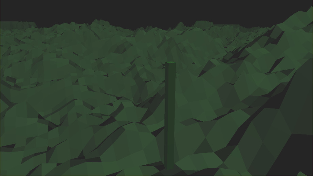
L-Systems a simple Tree
After learning some openGL basics i decided it was time to combine fragments i already knew like phong-lighting and Camera transformations with new aspects. I came across L-systems which can be used to create plant like geometry. Since i was intrigued by the results that can be achieved i wanted to try it myself.
In general L-systems are a set of symbols (or elements of a set) that define a Alphabet. Each Symbol has a meaning in our graphic System. For this project I choose a small set.
$$ Alphabet := { F, G, *, /, +, -, [, ] }\ Axiom := { F } $$
Next each element was assign a function within the actual graphics system.
$$
\begin{aligned}
\textbf{F} &:= \text{Draw a basic shape (here a cuboid)}\\
\textbf{G} &:= \text{Translate}\\
\textbf{*} &:= \text{Rotate by } \theta \text{ around X-axis}\\
\textbf{/} &:= \text{Rotate by } -\theta \text{ around X-axis}\\
\textbf{+} &:= \text{Rotate by } \theta \text{ around Z-axis}\\
\textbf{-} &:= \text{Rotate by } -\theta \text{ around Z-axis}\\
\textbf{[} &:= \text{Push CTM on stack}\\
\textbf{]} &:= \text{Pop CTM from stack}\\
\end{aligned}
$$
So with a given String the corresponding geometry can now be created. The code for each element is fairly straight forward:
 case 'G':
     //Translate
     model = glm::translate(model, glm::vec3(0.0f, objectHeight, 0.0f));
     break;
 case '+':
     //rotate +angle -> Z-Axis
     model = glm::translate(model, glm::vec3(-xzCorrection, -yCorrection, 0.0f));
     model = glm::rotate(model, angle, glm::vec3(0.0f, 0.0f, 1.0f));
     break;
Now looking back at the project I realise that the correction factors would be obsolete if I had simply translated by a little less than the actual objectHeight. Anyways the code for actually drawing is a little bit messy since i didn’t know about instancing at the time so for each drawcall all the points of the cuboid are send to the GPU which leads to quite a few problems as we will soon see.

$$ \textbf{F} \implies \textbf{FF+[+F-F-F]-[-F+F+F]*[*F/F/F]/[/F-*F*F]} $$
Challenges
However we faced a few challenges some originate in the fact that this replacement generates a massive String with very few iterations the application faces a few limitations.
- Since for each Frame the data for each cuboid is resend individually. Furthermore I used GL_Triangle which means that each cuboid requires 864*6*4 Bytes = 864 Bytes for every cuboid that is drawn.
- The generation of the String is implemented very simply and takes up a lot of memory. So even if a system would manage to somehow overcome limitation 1 it would crash after running out of memory after just a few iterations.
- OpenGl only supports a local lighting model which means that “leaves”(which are still cuboids) are rendered the same no matter if they are on the site of the tree that faces the lightsource or on the opposite site.
I tried to address issue 1 and 3 however since i was and still am fairly inexperienced these attempts are only workarounds.
Transform on CPU once
Instead of sending the ctm and cube-points for each cube individually to the GPU and doing the transformation on the GPU. I decided to transform all cube once on the CPU and then send all the points at once to the GPU, which means the amount is still the same however since it is precalculated and continuous it is a lot faster. Obvious downside is that i can no longer dynamically change any attributes without letting the CPU recalculate. Thus every time one wishes to step to the next iteration (or previous) the CPU has to recalculate all the points. However once the points have been calculated the tree can be viewed smoothly.
Assuming the tree is a cylinder
As for the problem with the local lighting model. I pass a center position to the shader-program from which i can calculate a diffuse value for the imaginary cylinder which is then interpolated with the actual diffuse value for the face. The effect is not realistic but looks somewhat believable or at least more believable than the actual diffuse value.
Below the source-code and binaries are provided if you want to look at the application yourself.
Controls:
| Key | Action |
|---|---|
| F1 | Toggle Wireframe drawmode |
| F2 | Toggle Point drawmode |
| F3 | Toggle Light-Source rotation |
| F4 | Toggle Static Draw (Attention if you are in static draw mode the following Action will not become visible until you exit static draw( and possible reenter for better performance) |
| F5 | Increase the angle which is applied for elements *,,+,- |
| F6 | Toggle light radius |
| WASD | Move the Camera |
| Shift | Toggle increased movement speed |
| Mouse | Orient camera |
| ESC | Exit |
Downloads: git-repository, Windows x64